Products
Categories
Advanced Trainers Power Electronics
SOLID STATE CONTACTOR USING IC 555, OPTO COUPLER, TRIAC
- To study that the output of the 555 timer is connected through the High power Triac based opto isolator triggers the Triac which in turn controls the speed of the motor
- Speed of the motor depends upon the frequency of the 555 Astable Multivibrator output.
FEATURES :
- 230V AC mains
- +12V/500mA
- HP AC Motor (not supplied)
- 4. Tacho meter (not supplied)

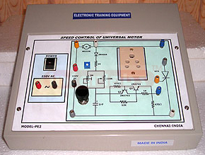
SPEED CONTROL OF MOTOR USING SCR
To control the speed of the AC motor, hand driller, etc, using SCR.
The gate is triggered by diac device to control the speed of motor.
The SCR conducts in one direction when it is triggered by positive voltage applied between gate & cathode. The trainer is operated with 230VAC/50Hz mains.
| Input Supply : | 230VAC/50Hz mains operated |
| Dimension : | 27cms x 17cms x 10cms |
| Weight : | 500gms |
CHARGER CIRCUIT FOR LEAD ACID CELL
- To Study the Lead acid Battery charger using 555.
- Battery charger for Lead acid cell can be built with a 555 timer at a considerable parts saving over similar circuits.
1. +10V /500mA
2. 230V main operated.
CHOPPER CIRCUIT USING COMPLEMENTRY
- study that the DC chopper converts a fixed voltage dc supply to a variable voltage d.c supply
- Study of class A,B, C & D circuits
- Triggering of chopper circuit is meant by SCR & UJT circuit
(i) +18V / 500mA
(ii) 230V mains operated
CONSTRUCTION OF VARIABLE DURATION TIMER
To design & study the two range 1-10 minute and 10-100 minute variable duration timer using IC 555, IC 4020
The output of the 4020 IC drives the transistor which turns "ON" the relay
(i) + 12V/500mA power supply
(ii) 230V mains operated
DC CHOPPER FIRING CIRCUIT
- Study of 4 line synchronised triggering pulse to fire thyristors connected in DC chopper circuit.
- The firing circuit is based on Ramp-comparator method. Isolation is provided by Pulse Transformer.
- Potentiometer to vary the firing angle from 180 to 0.
(i) Power Supply: +12V/500mA
(ii) Mains: 230V mains operated
DC CHOPPER POWER CIRCUIT
- To study that the DC chopper converts a fixed voltage dc supply to a variable voltage d.c supply study of class A,B, C & D circuits
- Triggering of chopper circuit is meant by SCR & UJT circuit
(i) +18V/.5A
(ii) 230V mains operated

DEMONSTRATION CAPACITOR
DESIGN AND CONSTRUCTION OF OTT FILTERS
To construct and study the characteristics of OTT filters using COMC and COML
Technical Specifications
- Built in regulated power supply + 28V /500mA
- Output power (PO) = 360W
- Output voltage (EL) = 120V(RMS)
- Output frequency (f) = 400Hz
- Rated load power factor (PF) = 0.7 lagging
DIGITAL TACHOMETER USING OPTICAL TRANSDUCER
- The speed of the motor can be varied precise angular positions within the encoder wheel
- Encoder wheel consists of Infrared LED and photo transistor is called interrupter circuit
- If you apply voltage to DC motor it rotates. Each slit causes the interrupter circuit to generate a pulse by counting the pulse that is displayed in the display
- As you increase the DC voltage the speed of the motor increases.
+5V /500mA
+12V /500mA
DIODE UNIT SILICON
DIODE VALVE MOUNTED
DRIVER CIRCUIT FOR LCD DISPLAY
- Study of BCD to decimal conversion
- This circuit incorporates 4553 BCD to Decimal Encoder / Display Driver and LCD 7 segment Display.
| INPUT: | Logic switches-4Nos |
| OUTPUT : | LCD Display |
| Power Supply : | +5V / 500mA |
FIXED CAPACITORS
HALF CONTROLLED RECTIFIER USING PUT
- Study of V/I characteristics of PUT
- Study of PUT as relaxation Oscillator
(i) +15V/500mA
(ii) 230V mains operated
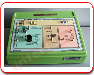
ILLUMINATION CONTROLLER USING LDR
- To study the illumination control using LDR & Triac
- LDR is connected as RC phase shift circuit applied as control signal to gate
- The firing of the Triac can be varied using LDR which in turn varies the intensity of the Lamp load
FEATURES :
- + 15V/500mA
- 30V / AC input
- 6V Bulb
- 12V Bulb
L-C COMMUTATION OF A THYRISTOR
To study that the commutation circuit uses additional LC components like COMC & COML to accomplish the turning off the thyristor
TRIGGERING CIRCUIT :
Relaxation oscillator using UJT.
Power supply
1. +15V/500mA
2. +18V/500mA
MINI MOTOR UNIT
MULTI TAP TRANSFORMER
N-P-N TRANSISTOR UNIT
OBJECT COUNTER WITH BUILT IN MULTIPLEXED DISPLAY
- To study 4 digit object counter using 555, IC 74928, LDR
- When an object hits the LDR output of 555 timer goes high 74928 counter activates the display to 0001.
(i) +5V /500mA
(ii) 230V mains operated.
P-N-P TRANSISTOR UNIT
PARALLEL INVERTER
1.To study the conversion of fixed D.C voltage to an A.C voltage of variable frequency or variable magnitude
2.Study of Gate Triggering circuit using UJT and pulse isolation Transformer.
3.Study of commutating circuits.
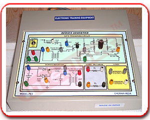
PE- 3 SERIES INVERTER
- To study the conversion of fixed D.C voltage to an A.C voltage of variable frequency or variable magnitude
- Study of Gate Triggering circuit using UJT and pulse isolation Transformer.
- Study of commutating circuits.
FEATURES :
- Built in regulated power supply : +18V /500mA
- 230V/50Hz mains operated
- Detailed step by step Instruction Manual
- Set of patching wires
| Mains : | 230V mains operated |
| Dimension : | 27 x 17 x 5cms |
| Casing : | Mounted in a sloping FRP cabinet |
PHOTO ELECTRIC CELL UNIT
PHOTO ELECTRIC RELAY USING SCR
Study of light activated Relay using LDR & SCR.
When light falls on LDR, gate drive is applied to SCR which turns ON and activates the relay. 1. +12V/500mA
POWER SUPPLY UNIT
POWER SUPPLY UNIT AC/DC
POWER SUPPLY UNIT HT
POWER SUPPLY UNIT HT
POWER SUPPLY UNIT LT
POWER SUPPLY UNIT LT
POWER TRANSISTOR UNIT
SEQUENTIAL TIMER USING 555
OBJECTIVES :
The objective of this experiment Is to cascade, or connect in series, a pair of 555 timers sequentially light a pair of LEDs.
555 Timer : TIME ON YOUR HANDS: With the monolithic integrated circuit 555 you can get accurate timing ranges of microseconds to hours, independent of supply voltage variations. This versatile device has a large number of interesting practical applications, especially for electronic hobbyists.
1. +5V / 500mA
2. 230V mains operated
SINGLE PHASE AC REGULATOR USING SCR
- To vary the positive and -ve half cycle of AC signal using two SCRS.
- Phase angle can be varied using Gate control circuit
- Gate Triggering circuit : Relaxation oscillator using UJT.
- Isolation Transformer : 1:1:1:1 Pulse transformer.
- Power supply: 18V/AC
SINGLE PHASE HALF CONTROLLEED BRIDGE CONVERTER
- Auto Transformer: To suit single phase 230V/50Hz input and to get 230V variable output at rated load.
- Isolation Transformer: To suit single phase 230V/50Hz supply load ratio 1:1, KVA rating to suit the load ratings.
- Power Circuit: Different power circuit configuration are possible using SCR's and diode modules.
- Half wave converter - 1SCRs
- Half controlled converter - 2SCRs & 2Diodes
- Fully controlled converter - 4SCRs or Triacs
- AC phase control - 2SCRs or Triacs
- Dual converter - 8SCRs.
SOLAR CELL UNIT
SPEED CONTROL OF DC SHUNT MOTOR USING SCR
To study that the speed of the DC shunt motor can be varied using SCR Circuit.
The firing circuit is based on Ramp - comparator method. Isolation is provided by pulse Transformer.
FEATURES :
Works directly on 230V AC mains.
Gate drive current of 200mA to trigger wide range of devices.
Test points to study the logic circuit
Soft start and soft stop feature.
Power supply : 12V/500mA
Dc motor with Tacho generator setup.
Digital Tacho meter
Digital multimeter
TEMPERATURE CONTROL USING 555 AND THERMISTOR
- To construct temperature controller circuit using 555 with a thermistor resistor spanider
- The timer turns ON the heating element. Built in regulated power supply: +9V/500mA
| Input Supply : | 230VAC/50Hz mains operated |
| Dimension : | 27cms x 17cms x 10cms |
| Weight : | 500gms |
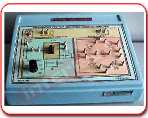
TRIGGERING CIRCUIT FOR BRIDGE RECTIFIER USING OP-AMP-780
- Study of bridge rectifier using two SCRS
- The Gate of the SCRS can be triggered by using Industrial op-amp IC 780
- By controlling the firing angle of the SCRS during each half cycle the duration of conduction of the SCR is varied and the DC output is controlled in accordance with the setting of the output voltage control.
- The trigger pulses can be shifted within a phase angle between 0 and 180
- This trainer comes with built in regulated power supply
(i) + 12V/500mA
(ii) 18V AC/500mA
(iii) Step by step Instruction Manual
(iv) Set of patching wires
| Mains : | 230V mains operated |
| Dimension : | 27 x 17 x 5cms |
| Casing : | Mounted in a sloping FRP cabinet |
TRIGGERING CIRCUIT FOR SINGLE PHASE CONVERTER
This unit generates four line synchronized isolated triggering pulse to fire thyristors connected in single phase (1) Half wave, (2) Full wave, (3) Half controlled Bridge, (4) Fully controlled Bridge and (5) AC phase control power circuit.The firing circuit is based on Ramp-comparator method. Isolation is provided by pulse Transformer.
FEATURES :
- Works directly on 230V AC mains.
- Gate drive current of 200mA to trigger wide range of devices. Provision for feed back control.
- Firing angle variation from 180 to 0 on a graduated scale.
- Test points to study the logic circuit.
- Soft start and soft stop feature.
- Neatly designed front panel.
This unit along with our SCR converter modules, Rectifier diode modules, Single phase half controlled converter power circuit and single phase fully controlled converter power circuit can be used to conduct Power Electronics Experiments on single phase.
FRONT PANEL DETAILS :
- POWER : Mains on/off Switch with built in LED Indicator
- FIRING ANGLE: Potentiometer to very the firing angle from 180 to 0 when the control switch is in INT position. \
- CONTROL: Switch for internal (INT) or external / feedback (EXT) control
- Vc: External control input when the control switch is in EXT Position. 0 to 5V.
- GND: Equipment ground for connecting external control input and to observe the test point signals.
- ON/OFF: Switch for trigger output with soft start and soft stop feature.
- TEST POINTS: To observe the signals at various points in the logic circuit for study purpose.
- TRIGGER OUTPUTS:
T1 & T1 For +ve Half Cycle.
T2 & T2 For -ve Half Cycle.
TRIODE VALVE MOUNTED