Products
Categories
Instrumentation Trainer Experimental Modules

AD 590 TEMPERATURE TRANSDUCER TRAINER. MODEL IBL-AM - 10
This Trainer makes use of AD-590 Semiconductor Transducer, for measurement. The trainer consists of a heat bar with provision for inserting four AD-590 Transducers. Only one transducer is supplied with the trainer. A built-in heater heats this heat bar. Using this trainer, AD-590 temperature characteristics can be studied.
Specifications:
- AD-590 Transducer fitted on a heat bar
- Heat bar Jig with heater.
- Provision to fix 2 numbers of AD-490 Transducers.

ANGULAR POTENTIOMETRIC TRANSDUCER MODULE. MODEL IBL-AM - 16
Angular potentiometric transducers are used in CNC machine controls, robotic controls, etc. The purpose of this transducer is to measure the angular rotation of a mechanical member subtended from its initial position. This trainer module consists of a graduated potentiometer from 0? to 250?. The output voltage of this is proportional to the angle subtended by this potentiometer. A plot between angular displacement Vs the output voltage is made, to determine the characteristics, of this transducer.
Specifications:
- Resistance: 1KW
- Angular rotation: 0? to 250?
- Output: 0 to 250mV DC, linear
- Built-in Power supply.

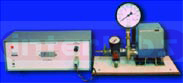
BOURDON PRESSURE TRANSDUCER DEMONSTRATION MODULE. MODEL IBL-INS - 4
Bourdon pressure transducer measure, pressure in a given instrument within some elastic limits. This is one of the varieties of pressure transducers. This transducer converts the applied force into a displacement. Therefore this is called as a force-summing device. The amount of displacement is a measure of the pressure exerted on this transducer. The range of pressure measurement depends on the material used and geometry of construction, namely circular tube or twisted tube.This tube deflects proportional to the applied pressure.
In Bourdon Pressure gauge, the measuring tube is arranged almost in a semi circular fashion. The arc of this near-semi-circular tube changes proportional to the applied pressure, causing large displacement at the farther end of this tube. A displacement transducer attached at this farther end is used to generate controlling signal to the indicating device. Bourdon pressure transducer demonstration module is an electronic instrument. This can measure pressures between 3 to 15 PSI. The output is 4 to 20mA. The current meter indicating this is linear representation of the measured pressure. The demonstration instrument has a pressure vessel. A foot pump (preferable to connect to a compressor) is used to increase air in the pressure vessel. The pressure vessel has a manually adjustable release valve to reduce the pressure, and set a predetermined pressure level.
A hand operated valve attached to the pressure vessel can also reduce the air pressure within the pressure vessel. This attachment significantly improves the understanding of the operation; this can be connected to a Data Acquisition instrument, Model DAS-1. An analog pressure gauge fitted to the vessel indicates the actual pressure for comparison. The electronics consists of power supply (to operate Bourdon pressure transducer), 4-20mA current meter, instrumentation amplifier, test points, and finally the analog output of the pressure transducer terminated on the two terminals for Data Acquisition purposes. A plot of an applied pressure Vs the analog output, or 4-20mA output gives the characteristics of the Bourdon pressure transducer. Hysterisis can be plotted. A useful attachment to this is I to P converter demonstration module.
Specifications:
- Input: 3-15 PSI (0.2 to 1Kg/cm2)
- Output: 4-20mA current.
- Built-in power supplies.
- Current meter to monitor output current.
- Air pressure by foot pump.
- 15 PJI Dial gauge.
- 2Lt Pressure vessel with manually adjustable relief valve.
- Pneumatic connections by FESTO make quick coupling connections.
- Built-in electronics.

CALIBRATION OF PRESSURE GAUGE OR PRESSURE TRANSMITTER USING MANOMETER MODEL IBL-AM-21
This setup is intended to measure low pressure gauges. The manometer is the metering device in this case, while the pressure gauge whose pressure is to be calibrated is used as DEVICE UNDER TEST (DUT). The manometer uses water for the measurement of pressure to be applied to the DUT.
Note: The same setup can also be used to calibrate pressure transmitters. The transmitter is not in the scope of supply. This is an optional pressure transmitter
Specifications:-
- Manometer: Suitable U-Tube manometer supplied for low pressure measurements
- Pressure gauge: Low pressure gauge supplied as DUT.
Optional Interface:-
- Low Pressure Transmitter: Low pressure measurement
- Input : 0 to 5PSI
- Output: 4-20Ma
- Necessary electronics is included in the setup

CANTILEVER BEAM DEMONSTRATION INSTRUMENT. MODEL IBL-AM - 12
Cantilever Beam consists of stainless steel beam fitted with strain gauge elements and displacement transducer. Load is applied by adding weights in the weighing pan, for different load conditions, the Young's modulus can be computed. Strain gauges, and displacement transducers, are two different elements used in this trainer. Four strain gauges are employed in bridge form to measure strain.
The stress component is given by the displacement transducer. By using these two inputs, Young's modulus can be computed by arithmetic. The arithmetic is to be programmed by you in the form of a program, using Computer Applications Trainer, Model DAS-1 or Microprocessor trainer Model MPT-85, with stress and strain components as input parameters. This demonstration module provides an academic exercise to see how simple cantilever measurements can be performed for different load conditions. This interface provides an experimental setup to study how an application oriented instrument works.
Specifications:
a) Strain Gauge Transducer:
- Material of the strip: stainless steel
- Length of the strain gauge foil: 10mm
- Thickness of the strip: 3.5mm
- Supporting line to leading point: 200mm
- Length of the strip: 300mm
- Width of the strip: 25mm
- Resistance of the strain gauge: 350ohms
- Excitation voltage: 9V DC
- Two strain gauges are mounted on one side of the strip. Two more on the other side of the strip.
b) Displacement Transducer:
- Displacement: 5mm
- Excitation frequency: 4Khz
- Excitation voltage: 1V pp
- Case: stainless steel
- All mounted on an elegant Jig.

CAPACITIVE TRANSDUCER MODULE. MODEL IBL-IM - 28

FLAPPER NOZZLE TRAINER. MODEL IBL-FNT-1
The role of flapper nozzle lies in its ability to generate a large output air pressure, by placing a small obstruction at the orifice (at the nozzle) of an incoming pneumatic signal. This trainer has a flapper nozzle, together with a pressure amplifier, suitably connected to a spring damper, and a spring compensator. This trainer not only used to draw the characteristics of a FLAPPER NOZZLE, but also highlights the application of a FLAPPER NOZZLE itself.
The Flapper Nozzle trainer is a pneumatic system. The air at fixed pressure enters a constriction (a partial obstruction) in its delivery path and enters a nozzle. The opening of the nozzle is larger than the constriction. When the flapper is moved away (usually one thousandth of an inch) from the nozzle, the pressure at the nozzle falls to a low value typically 2 to 3 psi. When the flapper is moved close to the nozzle, the pressure at he nozzle rises to the supply pressure. This pressure is now applied to a pressure amplifier, which in turn moves a beam. The purpose of this beam is to demonstrate the utility of a flapper nozzle experiment. The displacement of this moving beam is proportional to the pressure developed due to the positioning of the flapper from the nozzle.
This trainer is intended to demonstrate what a flapper nozzle is, and how it is used in typical pneumatic installations. Using this trainer the students / trainee can make measurement and draw graphs that describes the role of a flapper nozzle. Graphs can be drawn between (a) Output pressure vs displacement of flapper nozzle, and (b) Output pressure vs the distance traversed by the walking beam. By doing so, they correlate complete characteristics of the flapper nozzle system. System in addition to study an application of a FLAPPER NOZZLE system itself, namely a control valve itself minus valve portion of it.

HALL EFFECT TRANSDUCER TRAINER. MODEL IBL-HAL-1

HUMIDITY SENSOR TRANSDUCER TRAINER. MODEL IBL-HS-1
Humidity is the measure of water vapour present in a gas. It is usually measured as absolute Humidity, Relative Humidity or Due point temperature. In this experimental setup we are measuring Humidity in terms of Relative Humidity. Relative Humidity is The Ratio of water vapour pressure actually present to water vapour pressure required for saturation at a given temperature. The ratio is expressed in percent. Relative humidity (RH) is always dependent on temperature.
In this trainer, an external optional DMM is used to measure the humidity in terms of voltage when it is in 2V DC range. The reading so obtained is direct indication of Relative Humidity in terms of percentage. This trainer has a humidity transducer capable of measuring RH in the range of 20% to 90%, a timer, an instrumentation amplifier, a precession rectifier and built-in power supply .

I TO P - P TO I TRAINER. MODEL IBL-INS - 3
The I to P and P to I trainer, is an extension of the I to P trainer. This is a combination of two transducers in one unit. The I to P takes 4 to 20 mA as input and provides, output pressure in the range of 3 to 15 PSI. Whereas P to I transducer takes 3 to 15 PSI as input and generates 4 - to 20 mA as output current. This trainer consists of one each of the above transducers. The output of I to P transducer is given as Input of P to I transducer. A pressure gauge indicates the output of I to P and Input of P to I transducers. Two separate current meters monitor the currents of both transducers.
A filter line regulation unit provides moisture free air to the trainer. Dedicated built-in DC power supply and interface electronics are provided with the instrument. In manual mode, a variable potentiometer provides current to the I to P transducer. Automatic mode is possible, when connected to Computer Applications Trainer, Model DAS-1. The user must provide 5Kg/Cm2 compressed air power from a compressor.
Specifications:
- I-P Transducer
- Input: 4-20mA current
- Output: 3-15PSI (0.2 to 1Kg/cm2).
- I/O threads: 1/4" NPT
- Zero and Span adjustment by screw adjuster.
- Coil resistance: 90() 5 ohms.
- Coil inductance: 10mH.
- Supply pressure: 1.4Kg/cm2
- Air consumption: 60Litres/Hr.
- Vertical mounting
- Dial gauge at upstream.
- Pressure vessel with pressure release valve.
- P-I Transducer
- Input: 3-15 PSI
- Output: 4-20mA.
- All pneumatic connections are made by using FESTO or similar make quick couplings.
- Current meter: To monitor input to I-P converter and output of P-1 current by switch selector.
- Built-in DC power supply.
- Selector switch to monitor current from internal current generator or from any external source.
- Pneumatic line to be provided by the user from any standard compressor, at 5kg/cm2.
I TO P TRAINER. MODEL INS - 2
Electro-pneumatic converter or I to P converter is one, which accepts 4 -20mA current (I) as input and converts into linear air pressure (P) in the range of 3-15 PSI. In process control, instruments, all the transmitter/receiver's outputs and inputs, are normally in the range of 4-20mA. (4mA are least value (0%) of FSD and 20mA is maximum value (100%) of FSD. A change in this current is used to indicate a change in flow, level, temperature, pressure, viscosity, load, speed, velocity etc. Hence, there is a need to have Electro-pneumatic converters from any of the above parameters to pressure and vice-versa. For example opening a valve and closing a valve. This valve in turn may allow air, water, oil, slurry etc to pass in controlled quantities. Hence, there exists a need to study what this Electro-pneumatic converter is all about. Electro-pneumatic converter experimental demonstration instrument consists of: 1) A stand alone 4-20mA current simulator. This simulator provides adjustable current in range of 4-20mA. A current meter monitors this. A selector switch selects either current from this simulator or from an external current source, operated by any other current source. 2) An Electro-pneumatic converter operating in the range of 3-15 PSI. Two pressure gauges connected on either side monitor upstream and down stream pressures. It is necessary to provide stabilized compressed air pressure as input, from any standard compressor. The upstream (from the compressor) pressure is more or less stable, while the down stream (from this converter) pressure keeps changing between 3 to 15 PSI, proportional to the current input to this converter. 3) This pressure can be monitored by a pressure gauge. I-P converter characteristics can be studied by tabulating the output pressures for various current inputs for forward travel (i.e. from 3 to 15 PSI) and backward travel (i.e. from 15 to 3 PSI). Therefore hysterisis can be plotted; the accuracy and linearity of the converter can be determined.
Specifications:
- Input: 4-20mA current
- Output: 3-15PSI (0.2 to 1Kg/cm2).
- I/O threads: 1/4" NPT
- Zero and Span adjustment by screw adjuster.
- Coil resistance: 90(+/-) 5 ohms.
- Coil inductance: 10mH.
- Supply pressure: 1.4Kg/cm2
- Air consumption: 60Litres/Hr.
- Vertical mounting
- Dial gauge at upstream.
- Pressure vessel with pressure release valve.
- All pneumatic connections are made by using FESTO or similar make quick couplings.
- Current meter: To monitor input to I-P converter.
- Built-in DC power supply.
- Selector switch to monitor current from internal current generator or from any external source.
- Pneumatic line to be provided by the user from any standard compressor, at 5kg/cm2.

INDUCTIVE TRANSDUCER MODULE. MODEL IBL-IM - 27

J-TYPE THERMOCOUPLE MODULE. MODEL IBL-AM - 8
Thermocouple Experiment Module is intended to study the behavior of a TC for different temperature zones. The scope of this equipment is restricted to study the temperature profile, and characteristic behavior of a J-type thermocouple. The experiment module is supplied with a thermocouple along with necessary electronics, excluding the power supply. Electronic Design Experimenter Model EDE-1 has
Specifications:
- One J-type Thermocouple.
- Boro-silicate Glass Jar.
- Thermometer.
- 100 Watt Heater.
- Require additional power supply.

LINEARLY VARIABLE RESISTOR TRANSDUCER MODULE. MODEL IBL-AM - 14
This trainer consists of a 1Kilo Ohm linearly variable resistor. This is connected to a voltage source. The output voltage is proportional to the displacement of this resistor's movable arm. The movable arm is connected to a micrometer jig. The displacement is measured in terms of mm. A plot between the displacement and the voltage exhibits the linear relationship. The trainer consists of the LVRT transducer, micrometer jig, and built-in power supply.
Specifications:
- Resistance: 1Kilo Ohm.
- Displacement: 15mm
- Output: 0 to 5V DC, linear
- Jig: Micrometer Jig included.
- Built-in Power supply.

LOADCELL EXPERIMENTAL MODULE. MODEL IBL-AM - 17
Load cell experimental module is a demonstration system. Using this trainer, the student can experiment, how a Load cell behaves for tensile and compressive loads. 1Kg Load cell is used to conduct this experiment. This Load cell is fixed on a mechanical structure (jig); which is used to experiment, both tension and compression. Assorted weights are supplied to add in steps of 50gm upto 1Kg. The output of the transducer is connected to the interface electronics, consisting of signal conditioner, instrumentation amplifier, adjustable gain data amplifier and a power supply. A digital display indicates the actual added weights, to the Load cell. Negative sign on the display indicates compressive load.
The Load cell is commonly used form of strain- gauge transducer. It converts an applied force (weight) into a bridge output potential. In a Load cell, the strain gauge is mounted on some form of a mechanical sensing element (column, beam et c.), and the gauge (or gauges) is (are) into a bridge configuration. Compensation of temperature and non-linearity is provided for by the manufacturer in the selection of resistance values for the arms of the bridge and in series with the bridge. Strain gauges are low-impedance devices; they require significant excitation power to get output at reasonable levels. A typical strain-gauge-based Load cell will have a 350Wimpedance.
Specifications:
- Universal type.
- Capacity: 1Kg
- Strain gauge impedance: 350 Ohms, connected in bridge configuration.
- Excitation: 9VDC
- Display: 3 1/2digit
- Power supply: Built-in
- Jig: Approximately 35x25cm. Provision to test, compression and tension.
- Weights: Assorted weights, to measure upto 1Kg in steps of 50gm.
- Interface: This works as an interface to any Data Acquisition system or to DAS-1.

LVDT EXPERIMENTAL MODULE. MODEL IBL-AM - 13
Linearly Variable Differential Transformer (or transducer) is a displacement transducer. This transducer converts mechanical displacement to proportional electric voltage. This experiment is primarily conducted to study the linearity of the transducer for a given displacement in it's operating range. The trainer is provided with a displacement (10mm) transducer. This transducer has a primary wind in and two similar secondary windings. The primary is connected to a SINE wave generator operating at 4Khz. Peak to peak output voltage is approximately 1V AC. Depending on the displacement, a mechanical core moves inside the transducer, permitting linkage of flux lines to it's secondary windings.
An output is available on both secondary windings, depending on the position of the core inside the transducer. A signal conditioner, instrumentation amplifier, gain amplifier, allows a proportional output at its terminals. To study the actual displacement in terms of millimeter, a micrometer jig is supplied. A plot between displacement Vs output is plotted to determine the linearity of the transducer. The same experimental module can also be used with data acquisition instrument to experiment on Data Acquisition techniques.
Specifications:
- LVDT Displacement: 19.99 mm (?10mm)
- Operating frequency: Approximately 4Khz with output of 1V AC RMS nominal
- Built-in power supplies
- Micrometer calibrating jig included
- Output Calibrated in terms of displacement on a 31/2 digit indicator with polarity indicator
- This instrument is assembled in an ergonomically designed cabinet.
- Separate output for connecting to X-Y recorder with 200mV DC FSD (?100mV)
- Operating at 230V AC single phase ?10% at 50Hz
- Working temperature at 43 ?10?C
OPTO-ELCTRIC TRANSDUCER TRAINER. MODEL IBL-DM - 3
PHOTO TRANSISTOR, PHOTO DIODE, LIGHT DEPENDENT RESISTOR (LDR), etc, are sensitive to light. Each exhibits a finite characteristic for incidence light. Wavelength and intensity of incidence light determines the output characteristic of the above devices. This trainer consists of one each of the above transducers. A common incandescent light source with variable intensity illumination is provided with this trainer. A separate output terminal for each transducer is provided for measurement. A plot between the intensity (for three different light intensities) and the output voltage is recorded. The trainer has built-in power supply.
Specifications:
- Opto devices: LDR, photo diode, photo transistor- 1 each.
- Source: A variable light intensity source.
- Built-in power supply.

PIEZO ELECTRIC TRANSDUCER MODULE. MODEL IBL-DM - 2
The Piezo electric transducer is one, which changes its state from mechanical to electric or vice versa. For example
a) when a Piezo electric crystal is subjected to mechanical vibrations, an electrical output is produced. This principle is used for measuring the vibrations in a mechanical fixture
b) When a Piezo electric crystal is excited electrically, the output is mechanical. This principle is used in audio buzzers.
Piezo electric crystals are used in seismic instruments. There are several electrical and mechanical considerations to design a Piezo for a specific application. In this trainer, four Piezo electric crystals are used. These are placed on a metallic platform on four sides of the plate. Each is separated by a distance of 3 to 4 inches. Four high - Zi amplifiers are used. Each amplifier is connected with one transducer at its input terminals. The outputs of all the amplifiers are connected to sample and hold amplifier, through a switch selector. Two separate sets of terminals, one before sample-hold, the other set after. In order to create a measured quantity, of mechanical vibration, a jig is provided. Using this jig it would be possible to drop 20gm weight from different heights. It is be possible to make qualitative study only.
Specifications:
- Transducer: 4 numbers of Piezo transducers placed on a jig.
- Selector: 4-position selector switch is used to check the output from each transducer.
- Output: Two separate sets of output terminals are provided.
- Output directly from signal conditioner, b) from sample and hold also.
- Jig: Included.
- Built-in power supply.

PRESSURE TRANSDUCER EXPERIMENT MODULE. MODEL IBL-AM - 19
Pressure transducer is used to measure the pressure in a given instrument. A pressure transducer is a secondary transducer. The member that is affected in the transducer is an elastic membrane, which does not directly reflect the applied pressure. Depending on the intensity of the pressure, this elastic membrane deforms or deflects proportional to the applied pressure. The resistance of the Strain Gauge (a primary sensor) connected on the other side of this membrane deforms and resistance change, proportional to the applied pressure, due to the deformation of the membrane. Four Strain gauge elements are inter connected in the form of a Whetstone's bridge. The imbalance of the bridge is a measure of the applied pressure on the elastic membrane. This trainer consists of a 1Kg/cm2-pressure transducer, mounted on a 2Lt-pressure vessel. A foot pump is used to inflate this vessel. A dial gauge mounted on this vessel indicates the pressure in the vessel. This gauge is used to verify the output of the pressure transducer and displayed. Interface electronics with built-in power supply, a pressure release cock are used in this instrument.
Specifications:
- Transducer: Strain gauge type with 350Wper element.
- Connection: Connected in bridge configuration.
- Excitation: 9V DC.
- Output: 0 to 5Kg/Cm2
- Dial gauge: 15PSI FSD dial gauge included.
- Jig: Pressure transducer, dial gauge, inlet cock, and pressure release cock mounted on the jig.
- Foot pump included Built-in power supply.

RTD TEMPERATURE TRAINER. MODEL IBL-AM ? 9
This trainer makes use of an RTD (PT-100), type thermocouple. Using this thefollowing measurements can be experimented.
a) Measure resistance of thermocouple for different temperatures.
b) Indicate temperature on digital indicator.
c) Provision to measure either actual temperature and amplified voltage.
d) Separate terminals are provided for connecting data acquisition trainer.
e) Provision for automatic switch ON or OFF, once preset temperature is crossed.
Specifications:
- One RTD Transducer.
- Boro-silicate Glass Jar.
- Thermometer, 100 Watt Heater.
- Built-in power supply
SOLAR PHOTOVOLTAIC CELL DEMONSTRATION. MODEL IBL-DM - 4
Solar cells at present furnish the most important long-duration power supply for satellites and space vehicles. It is also used in street lighting on experimental basis, in several places. This is one of the major thrust areas for producing power, using non-conventional energy. Since the current produced is very small, many P-N junction photo diodes are connected in series-parallel combination to achieve the desired voltage and current. This is called photo voltaic cell array. In this demonstration instrument, when no light is applied to a solar cell, the output voltage is zero. For ambient light, the solar cell produces some voltage, which is fed to a signal conditioner. The voltage produced in solar cell, is amplified by three times and displayed in a digital panel meter. The solar cell used in this trainer has maximum output voltage of 0.5V. An amplifier increases this by three times and produces 1.5V DC at its output terminals. By applying variable light intensity. We can observe the corresponding O/P voltage, and the characteristics of the solar cell can be recorded. EXPERIMENT: To study the characteristics of Solar PhotoVoltaic Cell, under 3 different light intensities. For ambient light, low intensity, and high intensity. Plot a graph of Output voltage Vs Distance of the light source. This observation can be recorded for 3 different light intensities.
Specifications:
- One Photovoltaic cell (0-0.5V Max).
- A concave lens to produce concentrated beam of light.
- Two concentric sliding tubes, one inside the other to adjust the distance, from light source to the Photo Voltaic cell.
- A built-in signal conditioner.
- Light source with variable light intensity.
- A digital panel volt meter (0-2V).

STRAIN GAUGE EXPERIMENT MODULE. MODEL IBL-AM - 11
Strain Gauge is a passive transducer. This is used to measure the lateral strain exerted on a given surface. This sensor converts a mechanical displacement into a change in resistance. Positioning and quality of bonding the sensor on the surface, largely determines the accuracy. An optional external Whetstone's bridge is used to measure bridge imbalance, which is a measure of strain. A bridge is symmetrical, four-element, circuit that enhances the instrument's ability to detect small changes in the sensor. Four Strain gauge sensors arranged in the bridge configuration, balances out fixed or quiescent voltage drop, allowing magnification of the different signal. This acquired signal is conditioned and computed to indicate actual strain suffered by the surface.
In the Strain gauge experimental module, the sensor is bonded on one end of a long rectangular stainless steel metal strip of uniform cross section. This end is fixed firmly to a metallic stand. The other end is freely suspended, similar to a Cantilever. To this free end, weights ranging from 50gms to 1000 gms in multiples of 50 gms are added to create strain (elongation) on the strain gauge strip. A relation between applied stress and measured strain gives the change in resistance of the gauge, explaining the principle of strain gauge transducer. This consists of a built-in power supply, interface electronics, assorted weights. A standard digital multimeter in 2V DC range is used to make voltage measurement. This voltage measurement directly indicates the weights added on the strain gauge pan.
Specifications:
- 4 numbers of 350 (strain elements connected in bridge configuration.
- Strain elements cemented on fixed end of metal bar. The other end is free to move.
- Two strain gauges are mounted on one side of the strip. Two more on the other side of the strip.
- Material of the strip: stainless steel
- Length of the strain gauge foil: 10mm
- Thickness of the strip: 3.5mm
- Supporting line to leading point: 200mm
- Length of the strip: 300mm
- Width of the strip: 25mm
- Excitation voltage: 9V DC
- Built-in power supply.
- Different weights, weighing upto 1Kg supplied.
STUDY CHARACTERISTICS OF ACCELEROMETER MODEL IBL-AM-22
This unit consists of an Accelerometer transducer. This is a demonstration setup. The accelerometer is a charge-sensitive device; an instantaneous change in stress on the internal PE element produces a charge at the accelerometer's output terminals that is proportional to the applied acceleration. Necessary signal conditioning is provided on the instrument.
Specifications:-
- Charge sensitivity: 45pc/g ? 55pc/g
- Frequency range: 2-2000Hz ?5% of FSD
- Capacitance: 1000pf
STUDY CHARACTERISTICS OF FLOW MEASUREMENT USING ROTOMETER MODEL IBL-AM-23
This is a flow measuring setup. It consists of a water tank of 25Lt. The water from the tank is pumped out by a pump. The output of this pump is passed through a Rotometer, which measures the flow rate in the range of 10 to 600Lt/min. The flow rate of the water is adjusted by suitable mechanism, there by achieving different flow rates. The water is set in re-circulation mode.
Specifications:-
- Water tank: 25 Lt.
- Pump: Self primining pump operating at 230V AC.
- Rotometer
- Service: Water.
- Connection: 1/2".
- Range: 0 to 10.5 LPM.
- Metering tube: Borosilicate.
- Float: SS 304.
- Needle: Provided, integral
STUDY CHARACTERISTICS OF VIBRATIONS MODEL IBL-AM-24
This trainer is intended to study the characteristics of a vibration platform. A plot of frequency of Oscillation Vs Amplitude of vibration is plotted. It is possible to set the frequency of oscillation from 100 to 1KHz. This trainer consists of a Motor, which provides rotation movement. It is possible to set continuously variable speed of this motor in the range of 100 to 3000 RPM. This has a top loading pan duly fitted with a soft sponge platform. A digital display reads the intensity of vibration. It is possible to observe the frequency of oscillation using an Oscilloscope or a frequency meter. This has built-in signal conditioners, power supplies.
Specifications:-
- Actuator : 230 V AC operated vibration shaker platform
- Loading : Top loading pan with sensors mounted for measurement of vibrations
- Display : 3 ? digit display to read the intensity of vibrations
- Frequency : Facility to read the frequency of operation.
- Interfaces : Necessary signal conditioners
- Power supply: Built-in power supply
STUDY OF CONTROL VALVE DYNAMICS. MODEL IBL-INS - 1
A flow control valve is a device used in process industry, which has function similar to a water tap at our homes. In a water tap, the quantity of water flow is regulated by rotating the handle of the tap, either clockwise or anti-clockwise. The quantity of water discharge is decided by the size of the tap. For larger sized tap, more water flows for the same opening, compared to a small tap. In flow control valve the operation of opening and closing is done remotely by pneumatic air pressure, in association with a control valve. The air pressure for opening and closing is used because, the fluid may be toxic or inflammable, or shear muscle power needed to control discharge of large quantities of fluid. Moreover I-P converter, which is used to open or close the flow control valve, can be remotely operated. Now there is a need to study two aspects of Flow Control Valve. 1) How to open and close a flow control valve under controlled condition. 2) The rate of discharge of fluid under consideration.
The scope of this module is restricted only to the study of opening and closing and not the fluid flow. The full potential of the flow control valve is experimented in FLOW AND LEVEL CONTROL TRAINER, when water is used as medium or PRESSURE CONTROL TRAINER, where air is used as medium of discharge. The control valve dynamics involve, the response time of the control valve from the time a control valve reaches a desired position. This time of actuation can be from fully closed condition to the fully open condition, or from and to a desired position of the stem. 2) Hysterisis study of a control valve. It is possible to position the stem of the control valve within the range of valve movement. It is possible to position the stem of the control valve by applying air pressure (in the range of 3 to 15 PSI), from fully closed position (0% opening), to the fully open (100% opening) position. Due to mechanical inertia of the control valve, the stem position is different for the same air pressure during upward travel and downward travel. This difference in stem positioning contributes to the hysterisis. Smaller the difference, the better is the control valve. By this experiment we now study, how good or how bad is the control valve. The study of flow control valve consists of single seated low flow control valve. The instrument is supplied along with necessary Electro pneumatic converter; current transmitter, current meter, DC power supply, and interface electronics, pneumatic connections by FESTO make quick couplings. Compressed air at 5 Kg/cm2 must be supplied by the user. Control valve position feedback is available for Data Acquisition purposes.
Specifications:
a) Control Value:
- Fluid: Water
- Body form: Globe-2-Way
- Size body/port/Cv: 1/2"- 1/4" - 2.0Gpm
- End connection / rating: Flanged RF - ANSI -150#
- Body material: CCS
- Trim form / Material: Contoured / SS304
- Flow chart/Direction: Linear / Under
- Actuator type: Diaphragm
- Control Signal: 0.2 - 1.0 Kg/cm2
- Valve action: Air to open
- Total stem travel: 18mm
- Equal percentage contoured low flow control valve.
- Input: 3 to 15 PSI air pressure.
- Two current meters to monitor a) input to I-P converter, b) Valve position.
- Filter line regulation unit.
- Interface electronics suitable for Data Acquisition instrument, Model DAS-1.
- 5kg/cm2 compressed air to be supplied by the user.
- FESTO make quick couplings.
- Electronics include, power supplies, Instrumentation amplifiers.
- Table top model.

STUDY OF D'ARSONVAL GALVANOMETER MODEL IBL-AM-26
STUDY OF SYNCHRO AS AN ERROR DETECTOR MODEL IBL-AM-25
Introduction:-
The shaft angle transducer is a fundamental component in modern control technology. It is difficult to define a mechanical system. By employing direct coupling or a straightforward mechanical translation, a shaft angle can be used to monitor either type of displacement.
Encoding Methods:-
The following types of shaft angle transducers are common to the control industry.
1. Potentiometer.
2. Incremental encoder.
3. Absolute encoder.
4. Resolver.
5. Inductosyn.
Potentiometer:-
The potentiometer houses a circular ring of resistive material. A rotating contact is positioned on the resistive material according to the input shaft angle. The resistance between one end of the ring and the contact is proportional to the shaft angle. If a voltage is applied across the Potentiometer, the voltage at the contact varies according to the shaft angle. This voltage can be routed to an A/D converter to derive a digital shaft angle.
This trainer is a demonstrator. In this trainer we use a potentiometric transducer. This transducer is connected at the output of the shaft under study. The shaft is capable of rotating in the range of 0 to 3600. It is possible to set the shaft in this range. This shaft in turn rotates the transducer by the angle displayed on the shaft?s dial. The output voltage is proportional to the actual angular position. There fore it displays the rotation angle interms of angle subtended by the shaft. The output is always with reference to the 00 only. This demonstrator is housed in an elegant cabinet with necessary signal conditioner, digital display etc.
Specifications:-
- Transducer: Potentiometeric
- Angle of rotation: 0 to 3600.
- Output: Calibrated display in the range of 0 to 3600.
- Shaft: The shaft acts as a rotating media. This can be rotated in the range of 0 to 3600 by using a knob.
- Scope of observations: Graph can be drawn Angle subtended Vs the display or rotation.
Accuracy: 2% of FSD

STUDY OF THERMISTER CHARACTERISTICS. MODEL IBL-AM-20
Thermistor is a thermally sensitive resistor. The Thermistor is a two-terminal component that may be used in either AC or DC circuits. It is manufactured in a number of shapes, such as beads, rods, disks, washers and flakes. Thermistors are often part of sensor devices used in temperature control. Flow measurement, voltage regulation, and such.
Using this trainer, it is possible to study and (a) observe the self-heating effect of current on the resistance of a Thermistor. (b) To determine experimentally the variation in resistance with time of current in a Thermistor (c) To study the Dynamic Characteristics of Thermistor.
This trainer has built in power supplies, Thermistor. It is desired to have additional 100mA DC current meter and high input impedance DMM for measurements.
TEMPERATURE TRANSDUCER PACK. MODEL IBL-PACK - 1

TORQUE TRANSDUCER EXPERIMENT MODULE. MODEL IBL-AM - 18
When a uniform metallic cylinder of finite diameter D and length L, which has one end fixed and the other end free to twist, twisted, then the cylinder suffers torsion. The deformation of the cylinder is a measure of torque. Strain gauge/s bonded on the surface of this cylinder, in strategic positions provides scope for measurement of torsion suffered by the cylinder. The experimental module has two mechanical parts, fastened. a) A torque transducer and b) 1 meter long bar of uniform cross section. One end of 1-meter long uniform bar is connected to the free end of the Torque transducer while the other end is connected to a weighing pan. Weights can be suspended at the other end of this bar, such that the torque transducer is subjected to angular rotation, but prevented, as the other end of this cylinder is fixed. Now a relation between the strain measured w.r.t. the applications of different weights are studied.
A built-in 3 1/2 digit display indicates the torque in terms of Kgm. For example, a weight of 1Kg, placed at a distance of 1-meter (1000 mm) from the transducer is indicated as 1000 on the digital meter. When the same weight 1-Kg placed at 500mm distance from the transducer it is indicted as 500 on the digital display. Thus for several weights in the range of 50gm to 1000 gms in multiples of 50 gms can be added. These weights are placed at different distances from the transducer, and the KgM characteristics can be studied. The trainer consists of torque transducer, Graduated 1meter long arm, instrumentation amplifiers, built-in power supply, and assorted weights. 3 1/2 digit display.
Specifications:
- Capacity: 1Kg
- Strain gauge impedance: 350 Ohms, connected in bridge configuration.
- Excitation: 9VDC
- Display: 3 1/2digit
- Power supply: Built-in
- 1-Meter long arm fixed on a metal chassis. The arm is graduated from 0 to 1meter in steps of 10Cm.
- Weights: Assorted weights, to measure upto 1Kg in steps of 50gm.
- Interface: This works as an interface to any Data Acquisition system or to DAS-1.
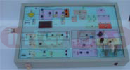
TRANSDUCER TRAINER . MODEL IBL-TDT-1
This is an integrated transducer trainer with the following transducers, built-in one unit. This is a FOUR-IN-ONE unit. This unit consists of the following four transducers.
a) THERMISTOR
b) HUMIDITY SENSOR
c) DC MOTOR CONTROL
d) STRAIN GAUGE

VARIABLE AREA CAPACITOR TRAINER. MODEL IBL-AM - 15
Capacitance exists between two parallel plates, when separated by a dielectric medium. The extent of capacitance depends on the common area subtended by these two parallel plates, separated by the dielectric. This principle is made use to create a variable area capacitor. The variable area capacitor is very widely used in oscillators to change the frequency of oscillations, in association with a RC network.
In this trainer, a variable area capacitor in the range of 50pf to 500pf is used to produce oscillations. These oscillations are converted to voltage. This voltage is measured on output terminals. A plot between the output voltage and the angle subtended by the transducer is plotted. An external power supply of ?12V and +5V are required.
Specifications:
- Capacitance: 50pf to 500pf.
- Angular displacement: 0? to 180?
- Output: 2.5 max.
- Power supply: External power supply required.